Hydraulics play a key role in erecting new San Francisco Bay Bridge
Customer:American Bridge/Fluor Joint Venture
Location: California
Self-anchored suspension span
The “signature” portion of the new bridge, being constructed by a joint venture of American Bridge and Fluor (ABF), is a self-anchored suspension span of length 1263 feet. Unlike a traditional suspension span in which the main cables are anchored at their ends and under tension, a self-anchored suspension span utilizes a single continuous main cable which forms a loop that is anchored in (passes through) the deck at each end of the span and passes up and over the support tower. As a result, the span is in compression.
Because of the nature of a self-anchored suspension span the deck must be completed first, and then the primary cable is placed and anchored to the deck. This requires falsework to support the deck until the primary cable and suspenders have been installed. In this case, some 18,000 tons of steel were required to construct the necessary falsework.
Hydraulics used to place deck sections
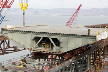
The bridge deck is being fabricated as “orthotropic box girder” (OBG) sections. The sections are barged as near as feasible to their intended locations and then lifted onto the falsework truss by a mammoth barge-mounted crane of nearly 2000 ton lift capacity. The deck sections are not placed directly onto the truss; rather they are placed on special cradles. “Each cradle serves as a large skid to support the OBG while it is being pushed,” explains Dan Hester of ABF.
A deck section resting on its cradle is pushed along the falsework truss by means of a “pushing frame” designed and fabricated by ABF. The pushing frame incorporates ten-foot stroke hydraulic jacks which are used to inch the cradle along the truss in a clamp-and-release fashion until the deck section reaches its ultimate location. According to Nick Greco of ABF, “About a day is required to push a section into place, and it’s about a one-week process to completely place and install a deck section.”
The time required to lift and push the massive deck sections (typically well in excess of 1000 tons each) can vary depending upon how close to their intended location they can be barged. Says Hester, “Some we only have to push a few meters because we are able to set them very near their final location. Because of their size, it is easier to set the OBGs away from the splice at least a few feet, and then use the hydraulic jacks on the pushing frame as well as the Enerpac jacks to adjust the piece to the correct orientation, slope, etc. to make the connection. The initial connection takes about six hours from when we make the first bolt until we have enough of the connection made that we can leave it for the night. It takes a couple weeks total to complete all the welding and bolting.”
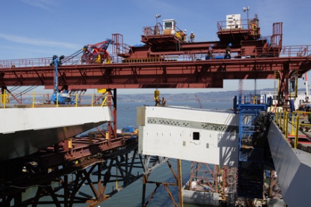
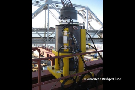
In Figure 1, left, a deck section has been placed on a cradle. Hester explains that “The bottom of the cradle is lined with polished stainless steel, and the cradle slides on top of Teflon® pads. The actual sliding surfaces are therefore stainless steel on Teflon®. This produces a friction coefficient of approximately 0.08.” When the deck section reaches its final location, the position of the OBG is adjusted by using the “jacking hats” with each cradle supported by four pairs of 400-ton, 6" stroke hydraulic jacks.
The jacks are used to align the OBG with the previously erected OBG so that the splice connections can be made. Greco explains that the OBG is both bolted and perimeterwelded to the preceding deck section. The number of “jacking hats” required varies because the deck sections are not all the same. “The jack pressures are also continuously monitored during splicing activities to verify that the local capacity of the falsework truss is never exceeded,” says Hester.
Strand jacks hoist cross-beams
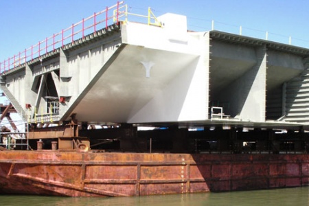
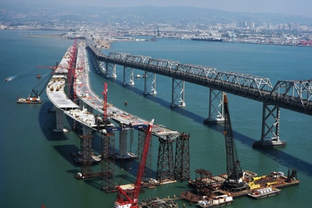
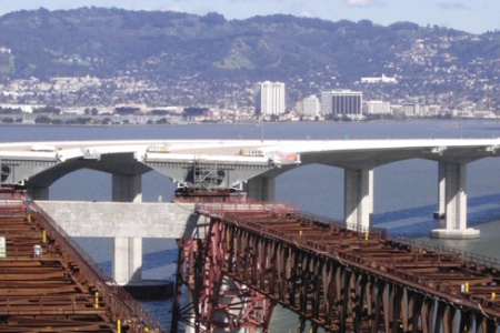
The new span will actually have twin, parallel decks (visible in the title photo), each providing five traffic lanes. Stability and stiffness are achieved in part by periodic cross-beams as indicated in Figure 2, right. The structure on its side provides the attachment point for a cross-beam linking the parallel spans.
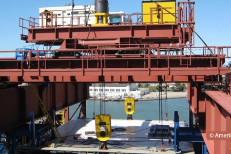
Because of tidal restrictions near Yerba Buena Island, the huge crane previously mentioned cannot be used to hoist the two westernmost cross-beams into place between the parallel spans. Greco explains that ABF designed and fabricated a gantry structure to lift certain cross-beams that could not be erected by the crane into place. The gantry straddles the two span-trusses and supports a transverse-moving carriage to provide X-Y positioning.
For the lifting mechanism on the gantry, ABF selected a novel strand jack system from Enerpac Integrated Solutions.
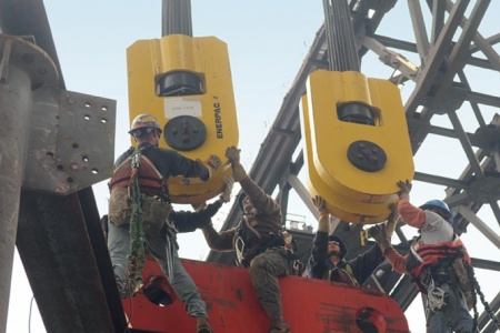
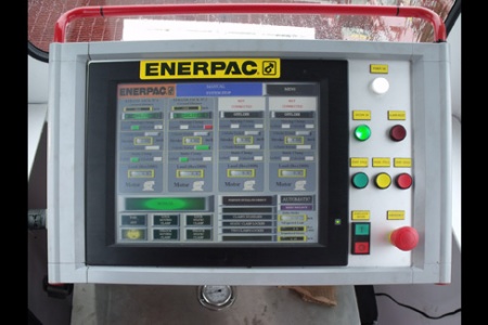
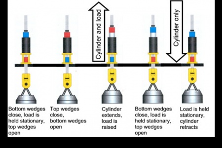
Each of the two 660 ton strand jacks is electronically controlled and networked to a digital controller. The jacks are intelligent devices with built-in sensors for closed-loop operation with the controller, and movement of the jacks is synchronized to within 0.04 inches. In addition to stroke and load alarms, the controller provides individual stroke and load readouts. The operating sequence of a strand jack is shown in Figure 3, left and the operator control panel is shown in Figure 4 lower left.
From accurate positioning of deck sections to precision lifting of cross-beams, state-of-the art hydraulics are facilitating construction of the Bay Bridge self-anchored suspension span. A forthcoming article will detail the role of digitally-controlled hydraulics in construction of the span’s 525 foot tower.
Peter Crisci is the Enerpac Integrated Solutions Business Leader for the Americas (www.enerpac.com).
<<< SIDEBAR >>>
The San Francisco-Oakland Bay Bridge American Bridge is not a newcomer to the San Francisco- Oakland Bay Bridge—the same company built the original (presently still in service) bridge in 1936. However, a portion of the original bridge was seriously damaged in a 1989 earthquake. After lengthy studies and deliberations, the state decided that reworking and seismically upgrading the old bridge would be more expensive in the long run than constructing a new bridge.
The new suspension span incorporates numerous earthquake- resistant features, some quite ingenious. For example, “hinge pipe beams” are inserted between sections. During an earthquake, the beams can function like a replaceable fuse, absorbing seismic energy. The beams are designed to be readily replaced if damaged in an earthquake.